Main results obtained in 2014
1. Introduction
Starting from the results obtained in the previous phases, during current stage the antennas and antenna arrays structures were optimized. The main objectives were the increase of the antennas directivity/gain and the increase of the operating frequency bandwidth.
For the dielectric membrane supported structures, two approaches were investigated in order to increase the radiation performances: a planar reflector placed below the membrane and the focusing of the electromagnetic radiated energy using a dielectric lens.
Using the previous reported results regarding the Substrate Integrated Waveguide (SIW) antenna for 35 GHz operating frequency, a similar antenna was optimized and measured for the 94 GHz frequency range. The experimental results were in good agreement with the experiment.
2. Experiments based optimization of the antennas and antenna arrays
Different techniques to increase the antenna performances were investigated. Fig.1 presents the comparison of the electromagnetic simulation results for 94 GHz membrane supported antenna for the following cases: the stand-alone antenna, the antenna placed on a reflector and antenna on reflector with a dielectric lens with a radius of 10 mm, thickness of 15 mm, placed at a distance of 3 mm from the antenna. An increase of the radiation gain with about 15 dB in the whole W-band (75-110 GHz) can be observed.
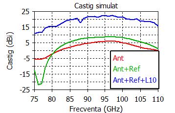
Fig. 1 Gain enhancement for the W band antenna: comparison between the simulated gain for the stand-alone antenna (Ant), the antenna on reflector (Ant+Ref) and the antenna on reflector with a dielectric lens (Ant+Ref+L10)
The mask set for the optimized membrane supported antennas is shown in Fig. 2(a) - the metalization mask, or the "frontside" mask - and (b) - the silicon etching mask, or the "backside" mask.

Fig. 2 Mask set for the membrane supported antennas and other test structures: (a) metelization mask; (b) silicon etching mask
Table 1. Measured performances for the W band antenna structures
| Measured performances | Initial structure |
Optimized structure |
Matching bandwidth |
88.238 – 105.83 GHz |
83.56 – 106.37 GHz |
Fractional bandwidth |
18.7% |
24.27% |
|S11|min |
–34.7 dB @ 95 GHz |
-47.4@92.6 GHz |
Table 2. Measured performances for the 140 GHz antenna structures
| Measured performances | Initial structure |
Optimized structure |
Matching bandwidth |
125 – 170 GHz |
125 – 170 GHz |
|S11|@140 GHz |
-18 dB |
-38 dB |
Maximum gain |
5 dBi |
6.2 dBi |
-3dB gain bandwidth |
130 – 155.5 GHz |
125 – 151.3 GHz |
The substrate integrated waveguide (SIW) antenna structure was optimized for 94 GHz operation. Fig. 3(a) shows the 3D radiation characteristic (directivity) at 94 GHz. Fig. 3(b) plots the gain as a function of frequency.
A matching bandwidth (defined for |S11| < –10 dB) between 90 – 95.62 GHz, with minimum reflections of –28.3 dB at 92.4 GHz were measured.

Fig. 3. Test structures fabricated in 2013: (backside view); (b) frontside view